|
|
| Copyright © Klaus Piontzik | ||
| German Version |
|
Strictly speaking, the current I and the flux density B can also be time-varying quantities
in the equation for the Hall voltage. If you limit yourself (initially) to sinusoidal shapes,
the frequencies used create resonance effects that can be used as a measuring device.
The Hall effect is usually operated with direct voltage, although the basic equation also allows other types of voltage, including sinuidal forms. If you take sine shapes for the current I and the magnetic field B, you get the following general equation for the Hall voltage: |
| 6.2.1 Equation |
|
The Hall voltage here is the product of two sine waves. This can also be easily implemented electrically
and used in such a way that magnetic waves can be detected. The novelty consists in setting the Hall sensor
to a defined operating point and then supplying it with an alternating voltage - similar to a transistor.
This creates the ejPi measuring method.
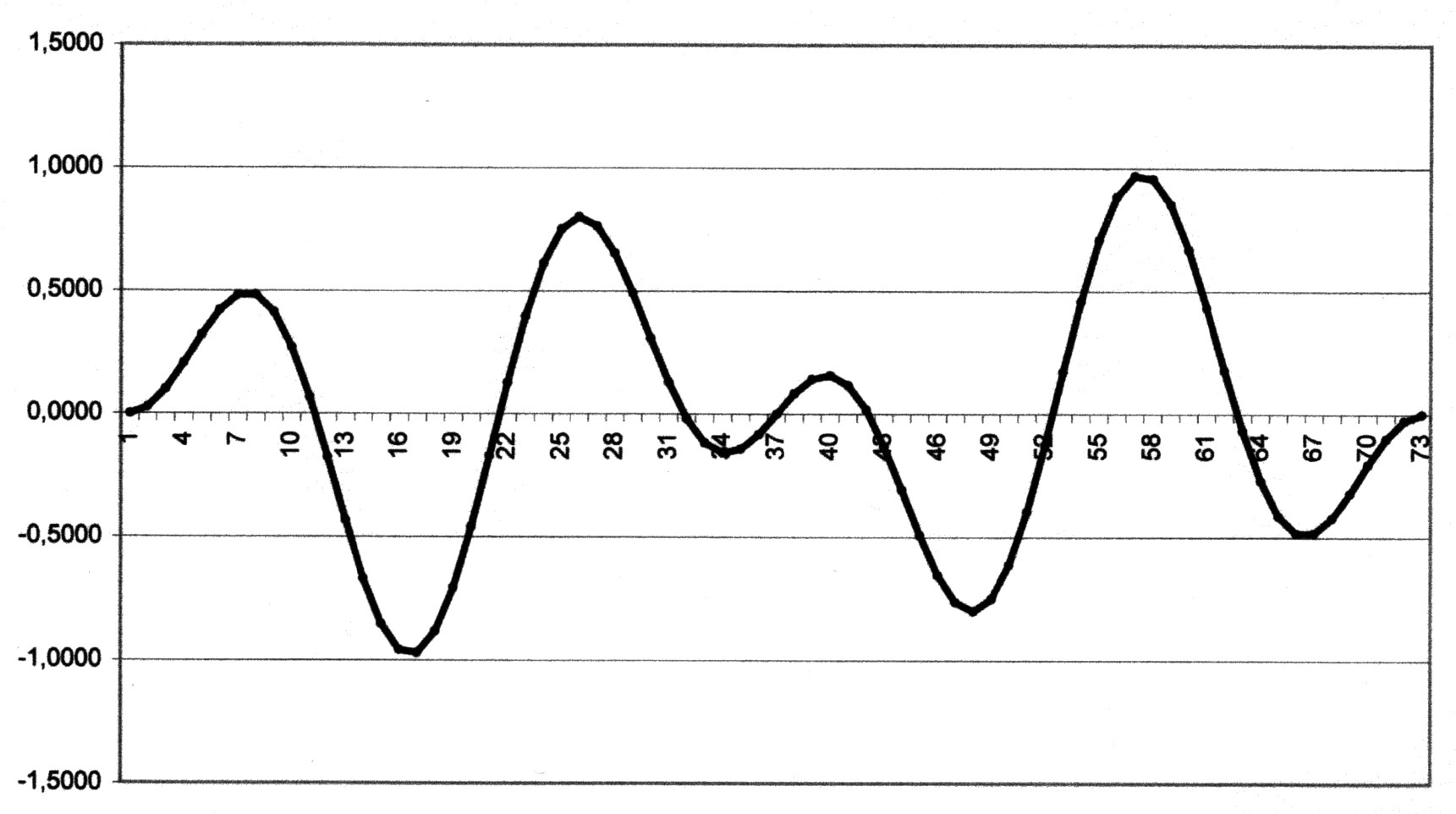
The Ebbers-Jähn-Piontzik measuring method, hereinafter referred to as the ejPi measuring method or also the ejPi method after its creators, allows the frequency measurement of magnetic waves. In the ejPi process, the Hall sensor is fed with a direct voltage (half the operating voltage), to which an adjustable alternating voltage is added. If you now place the sensor in a sinusoidal magnetic field, the Hall voltage UH obtained represents a multiplication of the two existing oscillations (supply current times magnetic field). The resulting oscillation is usually a beat shape, as shown in the following illustration 6.2.1. |
 |
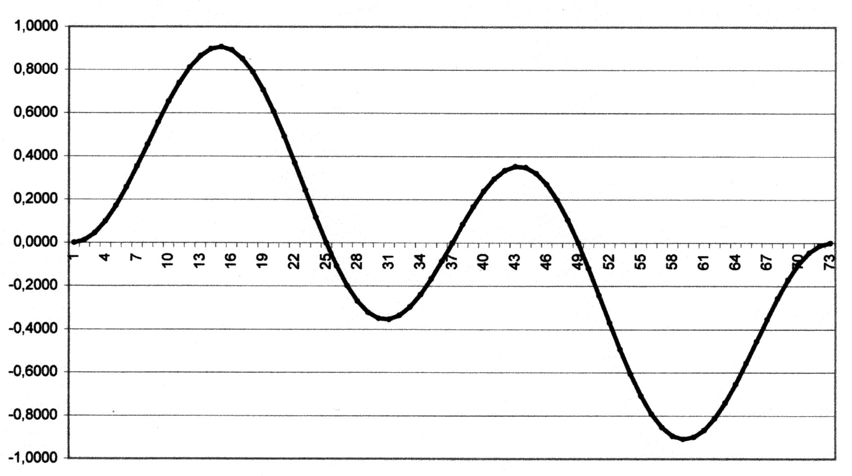 |
| Illustration 6.2.1 – Beats |
| At the same frequencies of the supply current and the acting magnetic field, a kind of resonance effect occurs - a clean square sine wave is created without negative voltage components, as shown in Figure 6.2.2. |
| 6.2.2 Equation |
| According to the addition principle for trigonometric expressions: |
|
cos 2α = cos (α+α) = cosα·cosα - sinα·sinα = cos2α - sin2α The following applies: cos2α = 1 - sin2α Insert into the equation above: cos 2α = cos2α - sin2α = 1 - 2·sin2α Rearranging the equation gives: |
| 6.1.2 Equation | |
| A clean cosine wave is created. |
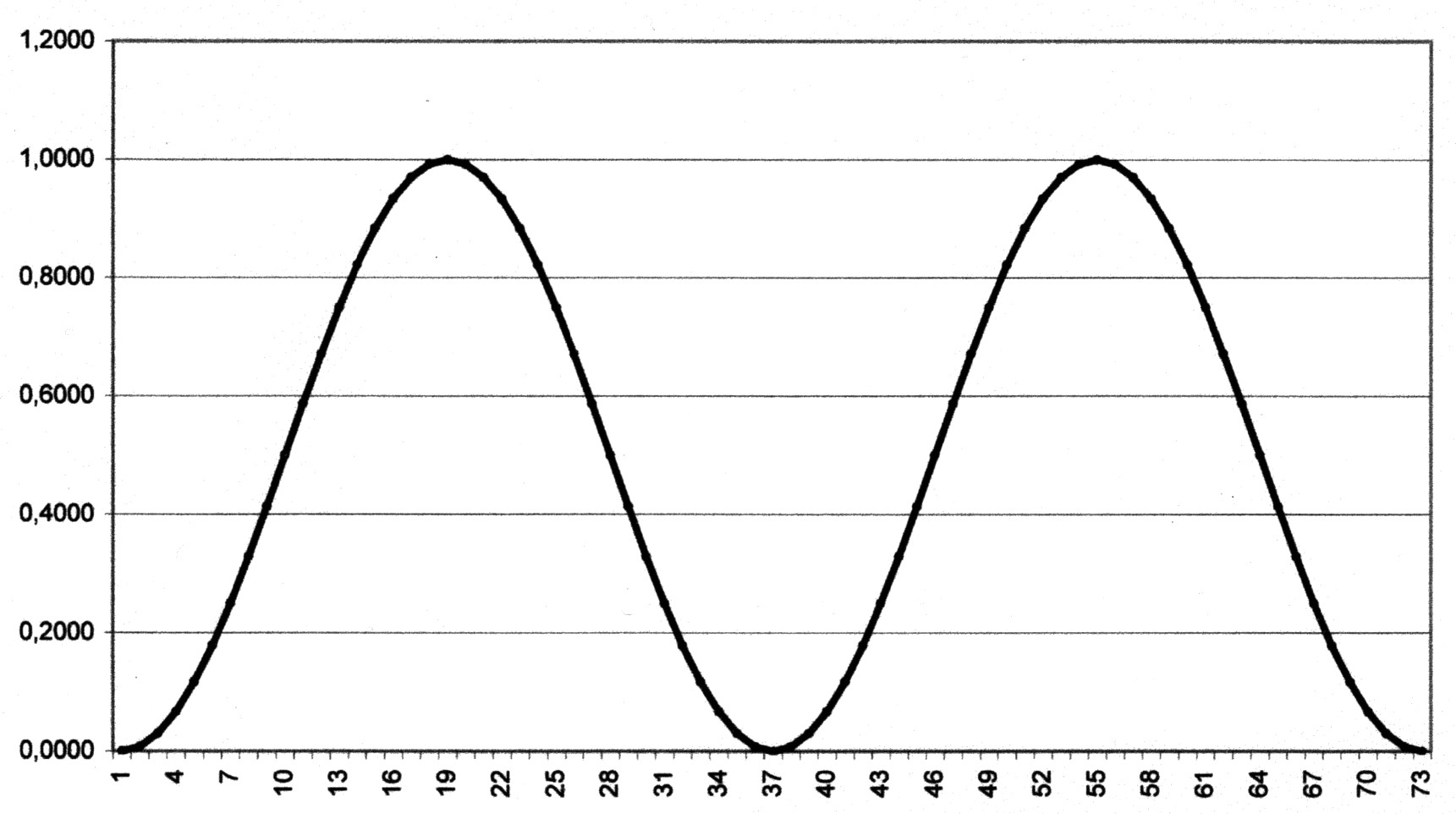 |
| Illustration 6.2.2 – Sine-square function |
| This resonance reaction can be
evaluated purely optically, using a measuring device (oscilloscope)
or by connecting additional electronic and digital components and
enables the recording or determination of the resonance frequencies that occur.
In any case, a Hall sensor with the classic four connections is required to generate the analog Hall effect. More modern integrated Hall sensors with three connections are unsuitable here. The ejPi measuring method allows the frequency measurement of magnetic waves. This can be used for measurement purposes in the areas of material testing, location and geophysics. The ejPi process is registered as a patent with the German Patent and Trademark Office under number 102012011759 |
|
200 sides, 23 of them in color 154 pictures 38 tables Production und Publishing: ISBN 978-3-7357-3854-7 Price: 25 Euro |
![]()