|
|
| Copyright © Klaus Piontzik | ||
| German Version |
2.2 - Addition and multiplication of waves
 |
 |
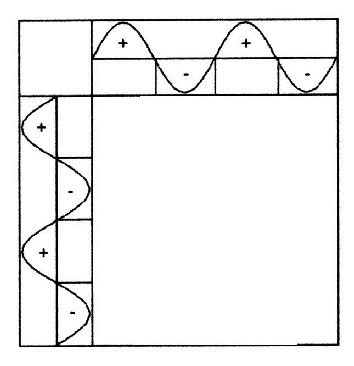
| Illustration 2.2.1 – Nullgitter | |
| The zero points of
both waves are transferred on the consideration level, as
shown in Illustration 2.2.1 right. This is a tesseral spherical harmonic with: G0 = sin α × sin β |
|
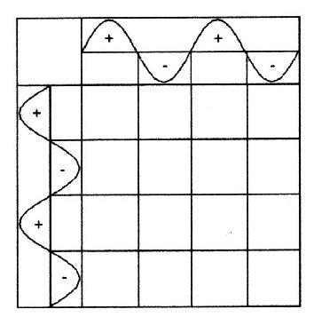
| Two vertical waves can be added by following qualitative rules: |
 |
2.2.2
- Pole forming: 1) + and + is + 2) – and – is – 3) + and – is 0 |
| Illustration 2.2.2 – multiplication |
| This procedure results in fields with different portents or different states. There exist three oscillations states: positive(+), negative(-), neutral(0) |
 |
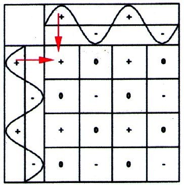
2.2.3
- Grid forming: It is striking that all zero fields are diagonal to each other. Connecting the zero fields as shown in Illustration 2.2.3.. |
| Illustration 2.2.3 – generated grid |
| 2.2.4 - Definition: | The (red)
grid-like structure is then called basic field or grid or generated field. The (blue) producing waves are
called basic
oscillations. The basic field: G = sin α + sin β |
| While the mathematical
concept of spherical harmonics does not ask for the cause
of the oscillation field, so the underlying waves must be
included on the physical examination. The term of the basic field does this. The basic field is defined by the basic oscillations. The name basic field is regarded as a physical equivalent to the mathematical concept of tesseral spherical harmonics. |
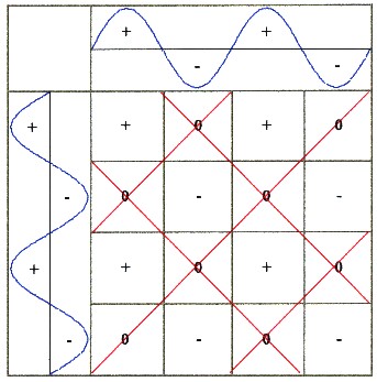
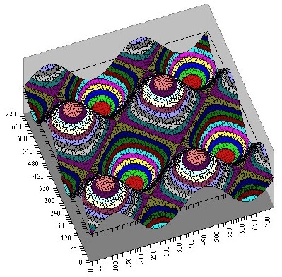
| The multiplication of the waves
works as seen first in a discreet manner
and way. A continuous point multiplication of two perpendicular to one another standing waves result in grid pattern, with alternating polarities of the grid fields, as in the illustration 2.2.4 shown. This shows that the field maxima and minima field points occur in the middle of the squares, while the lines consist of zero values. The field maxima are there as hills, while the valleys are formed by the field minima. |
 |
 |
| Illustration 2.2.4 – generated grid |
| On the bottom left and right in the left image the generating oscillations are visible. It is also visible that two generated grid fields result in an (generated) oscillation. |
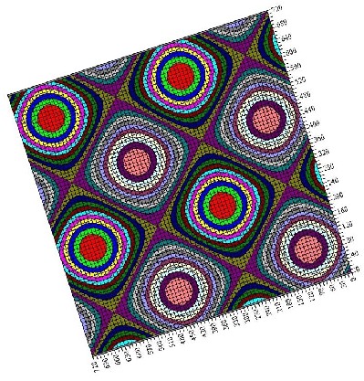
| 2.2.5 - Definition: | Grid = two-dimensional oscillation structure |
| It is possible here to draw a
second grid. It is the maximum grid. It combines the
field maxima and minima, so the top of the hill and the
valley bottoms in the illustration 2.2.4 and represents
the extreme gradient of the field. This allows two perspectives of the grid: |
| 2.2.6 - Definition: 1) the generated grid is described in the plane of basic oscillations with: G = sin α + sin β 2) The generated gird is described in the grid plane itself: G = sin φ × sin λ Both coordinate systems differ, they are turned against each other by 45 degrees. For Illustration: A physical analogue to the ground field are the |
| Chladni-figures |
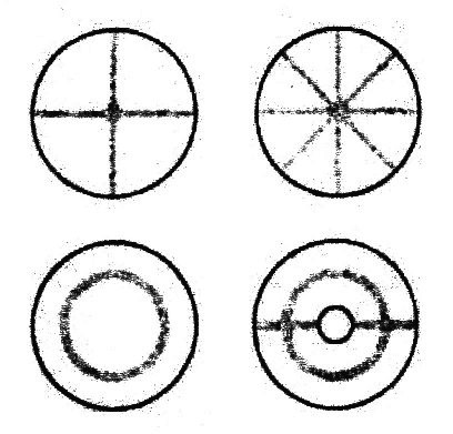 |
| Illustration 2.2.5 – Chladni-figures |
| For producing the figures, a metal
plate is sprinkled with sand and then moved to vibration.
When resonance occurs at certain frequencies with the natural frequencies of the plate, than the entire plate begins to oscillate. Thus, the sand exactly in the places stays where the amplitude of the vibration is zero. |
|
200 sides, 23 of them in color 154 pictures 38 tables Production und Publishing: ISBN 978-3-7357-3854-7 Price: 25 Euro |
![]()